

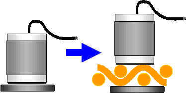
 The PosiTector 6000 FS (Screen Printing) was developed to accurately and non-destructively measure mesh, emulsion and stencil thickness, as well as substrate and dry ink deposit thickness. The PosiTector 6000 FS uses the magnetic induction principle to quickly measure the thickness of nonmagnetic materials.
Silk Screen Printing Origins
The modern silk screen printing process was patented in 1907. It involved silk stretched on frames to support hand painted stencils. In 1914 the process was expanded for multicolor printing with a screen process. At this time silk screening popularity increased and an industrial printing process for flags, banners and advertising signs in stores began. While quality improvements have been made in the equipment and materials used for silk screen printing, little has changed in the actual process. Today, screen printing is used everywhere. Applications include store displays, posters, advertising boards, electronic equipment marking, textiles, clothing and bumper stickers.
Screen Printing Process
The process begins with a fine nylon mesh stretched over a wooden or aluminum frame. The mesh is coated with a light-sensitive emulsion or film that, when dry, blocks the holes in the mesh. The image to be printed is output onto a film transparency. The positive film transparency and coated mesh are placed together and then exposed to ultra-violet light. A jet of water is used to wash from the screen any of the emulsion that has not been hardened by the ultra-violet light, creating a stencil corresponding to the image on the film.
The screen is fit to a press and a substrate to be printed is placed under the screen. Ink is placed on the top side of the screen and a rubber squeegee blade is pulled across the top of the screen, pushing the ink through the stencil onto the substrate. When printing multiple items the squeegee floods the screen again with a return stroke. Each item is then heat cured to permanently set the ink. The process is repeated as often as required for multi-colored items.
Mesh Thickness Measurement
The PosiTector 6000 FS (Screen Printing) gage was specifically designed for thickness measurements on fabric and stencils. The wide surface of the probe bridges the mesh openings enabling the probe to consistently measure from knuckle to knuckle of the mesh and stencil. Since during the tensioning process, the thickness of the mesh changes as compared to the thickness identified by the manufacturer, it is important to determine the mesh thickness on a stretched screen at printing tension.
After zeroing the FS probe on the included ferrous base plate, the gage is ready to provide an accurate thickness measurement of any substrate or screen mesh placed flat against the base plate.
Accurate mesh thickness measurements are important as they are a critical factor in formulas used to predict a mesh's wet ink deposit. Due to variations in screen mesh thickness, repeatability can be improved using the statistics mode available in selected models. With statistics enabled, the gage automatically calculates a running average of the readings taken. The measurement range of the FS is up to 60 mils (1.5 mm). The FS has a variable accuracy of 1% and up to a 0.05 mil (1 micron) resolution.
Stencil Build-Up Thickness Measurement
The ability to measure the thickness of the mesh and stencil enables the user to predict and control critical elements of the screen printing process. For process control it is necessary to control mesh and emulsion thickness across the surface of the stencil. Stencil thickness should also be periodically inspected with a PosiTector 6000 FS gage, particularly for shops that manually coat their screens.
For general printing of non-ultraviolet ink applications and jobs that do not require extreme detail, an emulsion build up of approximately 20 percent of the mesh thickness usually provides excellent print resolution and edge definition. A measurement of 20 percent EMR (emulsion over mesh ratio) provides enough emulsion build-up on the print side to effectively lift the threads off the surface of the substrate at the shoulder of the print reducing any loss of printed image by allowing the ink to fill the entire image area.
Applications involving fine detail, multi-color or ultraviolet printing require thinner overall stencil thickness. 10 percent EMR is more common as it provides the stencil just enough relief from the mesh on the substrate side, but still reduces total screen thickness (mesh plus emulsion) so that very fine detail can release from it without bleeding.
The thicker the mesh, the thicker the emulsion coating required to encapsulate the mesh and form a stencil with a smooth stencil surface (Rz-value). Thinner mesh is usually easier to coat, and provides a smoother stencil at a given thickness.
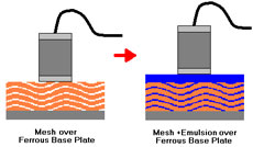
Stencil Thickness
To determine the thickness of build-up on the stencil, it is first necessary to zero the FS probe on the stretched mesh. By placing the included metal base plate under the mesh and attaining an average zero value (to account for variations in the mesh), the mesh becomes the zero value. Now when measurements are taken on the coated screen the gage will display the EOM (emulsion over mesh) build-up on the screen. As with all rough substrates or coatings, better repeatability can be obtained by calculating the average of several measurements.
Measuring Emulsion Thickness
If the emulsion coating is too thin, it will not provide a proper gasket seal. The ink will bleed underneath the stencil. This will cause the print to have rough looking edges (saw-toothing). Other symptoms of inadequate emulsion thickness include smeared images, dot loss in the highlights and dot gain in the shadows. If emulsion build-up is too high, the print shoulder will have too high of a vertical wall or column, and the ink may or may not completely fill into this area. If the ink doesn’t fill the area, the resulting print will show voids. If the ink does actually fill the column it may not release properly during printing. Even when the ink does release, too much ink may deposit into the image.
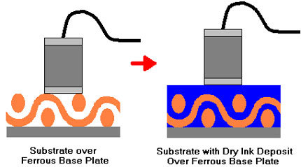
Dry Ink Deposit Thickness Measurement
Using a similar process to Emulsion measurement, the Dry Ink Deposit Thickness can be attained. Place the bare substrate over the metal base plate and zero the FS probe. After attaining an average zero value (to account for variations in the substrate), the substrate thickness becomes the zero value. Now when measurements are taken on the printed substrate the gage will display only the thickness of the dry ink deposit.
The measurement of dry ink deposits on substrates clearly demonstrates the advantage of electronic gages over most mechanical thickness measurement devices (calipers and micrometers). In addition to its accuracy and simplicity, an electronic gage can easily measure any area of a print without the need to cut the substrate to attain access for the measurement device.