
Conformal Coatings on Printed Circuit Boards
We offer hand-held, non-destructive coating thickness gages that are ideal for measuring the dry film thickness of conformal coatings on Printed Circuit Boards (PCBs).
Selection of the best solution depends upon:
- The substrate material beneath the conformal coating (fiberglass only, fiberglass with a copper ground plane, or fiberglass with copper traces),
- The size of the unpopulated area,
- The specified thickness range of the conformal coating.
Solution #1 : for PCBs with copper ground planes
Solution #2 : for PCBs without copper ground planes
Solution #3 : for PCBs without surface access
Solution #1 : For PCBs with copper ground planes
6000 Series eddy-current gages provide a low cost and simple solution for Printed Circuit Boards with copper ground planes. Probe selection is dependent on the size of the unpopulated area, the expected thickness of the conformal coating, and the desired probe resolution (see Table 1).
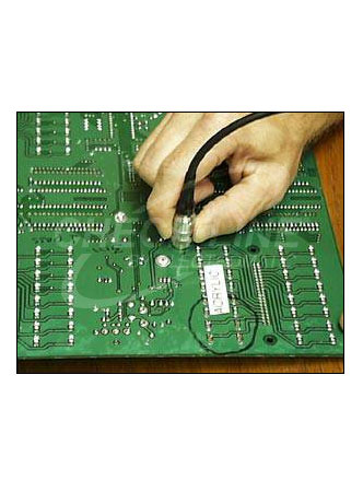
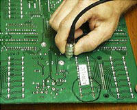
Measurements must be taken directly over a copper ground plane in an unpopulated area of the PCB (see Fig.1). For best accuracy, it is necessary to zero these gages on the solder mask before measuring the conformal coating thickness.
The 6000 NS1 is the simplest, most cost effective solution. At slightly higher cost, the 6000-NAS1 has greater measurement resolution. For hard-to-reach areas, the 6000 N0S1 has the smallest diameter probe tip and is useful for measuring smaller unpopulated areas of the PCB. To reduce operator influence, an optional probe fixture stand is available.
Basic Gage Models |
Probe Diameter |
Measurement |
Resolution |
6000 NS1 |
16 mm |
0 to 1500 ìm |
1 ìm |
6000 NAS1 |
16 mm |
0 to 625 ìm |
0.5 ìm up to 100 ìm |
6000 N0S1 |
5 mm |
0 to 625 ìm |
0.5 ìm up to 100 ìm |
Table 1: Basic 6000 Series eddy-current models. Standard and memory versions are also available.
 |
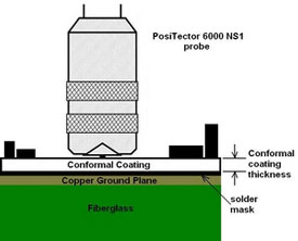 |
Fig.1: A 6000-NS1 measures on an acrylic coated printed circuit board with a solid copper ground plane
Solution #2 : For PCBs without copper ground planes
Our ultrasonic PT-200 B/Std gage measures conformal coating thickness on some printed circuit boards without a copper ground plane. Ultrasonic measurement has limited application on PCBs because the probe cannot be zeroed on the solder mask and because the layered structure of most PCBs can produce occasional false thickness values. Some applications work well such as thick silicone measurement or measurement over 2-layer boards. Contact our technical support staff to ensure an ultrasonic solution will work for your application.
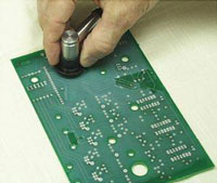
The PT-200 B/Std has a measurement range of 13 to 1000 microns (0.5 to 40 mils) with a resolution of 2 ìm (0.1 mil). The 30 mm (1.2”) diameter probe requires a relatively large unpopulated area (see Fig.2) although the actual measurement area is only 8 mm (0.3”). A drop of water serves as couplant during the measurement process.
 |
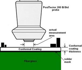 |
Fig.2: A PT-200 B/Std measures on a silicone coated printed circuit board.
Solution #3 : For PCBs without surface access
Some printed circuit boards are so heavily populated that a probe cannot access the surface. We suggest the use of the “substitution method” in which a metal coupon is inserted into the coating process and is coated alongside the board.
If a non-ferrous metal coupon is used, a conventional eddy-current 6000-NS1 can be used to measure the conformal coating thickness on the coupon. On a ferrous metal coupon, a magnetic 6000-FS1 would be required.
Background on Conformal Coatings
Conformal coatings are applied to Printed Circuit Boards to protect the mounted electronic components from contaminates such as dust, sand, moisture, salt mist and conductive particles. They provide environmental and mechanical protection to significantly extend the life of the components and circuitry. Typically only a few mils thick, conformal coatings also provide resistance to several stresses including abrasion, shock, temperature, ozone and ultraviolet degradation. They enhance performance and allow greater component density due to increased dielectric strength between conductors.
Conformal coatings used on printed circuit boards are typically acrylic or silicone, but may also include epoxy, urethane, parxylene (parylene), and UV-curable coatings. They are traditionally applied by dipping, spraying or simple flow coating, and increasingly by select coating or robotic dispensing.
The original military specification for Conformal Coatings dates back to 1966. They have evolved since then from solvent-based coatings that took hours to cure, to non-solvent based coatings that are quickly cured in minutes with the use of low heat.
Printed circuit boards are used to mount electronic components. Modern printed circuit boards use surface mounting techniques and typically have parts on both sides. The most common board material is FR4 fiberglass but they may also be constructed of phenol or Teflon. Most boards are composed of between 6 to 8 inner layers composed of the following materials from top to bottom:
- Solder resist
- Copper (traces/pads used as a ground plane)
- Fiberglass (substrate material)
Note: Layers 2 and 3 are repeated for “multi-layer” applications
Why measure?
Printed circuit board manufacturers would mainly be interested in controlling conformal coating application costs while ensuring adequate coverage.
A printed circuit board customer would primarily be interested in measuring conformal coating thickness as part of an incoming inspection routine. The quality of the conformal coating may be critical in preventing long-term product reliability issues after assembly.